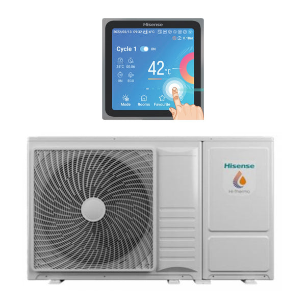
This article documents the reverse engineering process of the Hisense H-NET protocol, used by certain heat pump systems for internal communication between the indoor controller and the outdoor unit. My goal was to understand the structure of this protocol and pave the way for custom integration with Home Assistant. The unit I analyzed, the AHZ-080HCDS1, is not supported by any official or community-developed integration. The system is composed of a monobloc outdoor unit and an indoor remote controller which communicates over a two wire interface where power and data are carried on a single pair of wires: this is what Hisense calls H-NET wiring system.
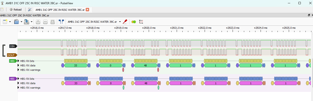
A closer inspection of the controller PCB revealed they’re using an MM1192 HBS transceiver: the H-NET protocol is indeed based on the Home Bus System at least at the physical layer. Who wants to dive deeper into the standard a good place to start could be this introduction from Analog Devices. Datasheet at hand I decided to tap into the data in and data out lines and take a look at them with a logic analyzer. Using Sigrok Pulse was pretty straightforward to figure out the transmission speed which turned out to be 9600 bps.

After countless hours of messing around and capturing data this is what I figured out: at the lowest level this is what a data frame looks like:
| SOURCE ADDRESS | CONTROL BYTE | MESSAGE LENGTH (len) | PAYLOAD | CHECKSUM |
|---|---|---|---|---|
| xx | xx | xx | xx … xx | xx |
| 1 Byte | 1 Byte | 1 Byte | (len – 4 ) Byte | 1 Byte |
Messages are broadcasted on the bus: there is indeed no destination address I could find. In my case the indoor controller address is 0x21 and the outdoor unit is 0x12. The control byte is used to acknowledge requests made on the bus: in this case the frame is composed only of the source address followed by a 0x06.
| SOURCE ADDRESS | CONTROL BYTE |
|---|---|
| 0x12 | 0x06 |
During my captures I never stumbled upon a NAK packet but I am confident the control byte could change to 0x15 — the standard ASCII code for NAK, as opposed to 0x06 which stands for ACK. This could lead to a retransmission of the corrupted message but it is just my guess. The message length is the total number of bytes transmitted, checksum included. The last byte is used for error detection and is computed using a simple XOR-based algorithm: the checksum starts with a 0x00 seed, performs a sequential XOR over all data bytes, and applies a final XOR with the source address. To figure out this I collected a good number of packets (~ 50) and I wrote a script to check with the most common checksum algorithms. Below is an implementation of the matching one in python :
checksum = 0
data = msg[:-1]src_address = msg[0]
for byte in data:
    checksum ^= byte
checksum ^= src_address
The communication seems to be always started from the indoor controller. Let’s talk about which data is actually transmitted: there is a 7 byte common header composed by a 1 byte MSG TYPE field, 5 consecutive 0x01 bytes and a 1 byte OPCODE that defines the operation/data structure of the message. These messages are sent approximately every 30 seconds. Let’s analyze the following message exchange: the indoor controller sends a status update, and the outdoor unit replies with a similar message.
| SRC | CTRL | LEN | MSG TYPE | – | – | – | – | – | OPCODE | OPERATION CMD | – | WATER SET TEMP | OPERATION MODE | DHW SET TEMP | POOL SET TEMP | CYCLE SELECTION | – | INDOOR TEMP 1 | AMB1 SET TEMP | ? | ? | ? | ? | ? | ? | ? | INDOOR TEMP 2 | – | – | AMB 1 ENABLE | – | – | – | YY | YY | MONTH | DAY | HH | MM | SS | – | – | – | – | – | – | CHECKSUM |
|---|---|---|---|---|---|---|---|---|---|---|---|---|---|---|---|---|---|---|---|---|---|---|---|---|---|---|---|---|---|---|---|---|---|---|---|---|---|---|---|---|---|---|---|---|---|---|---|
| 0x21 | 0 | 48 | 1 | 1 | 1 | 1 | 1 | 1 | 0xB1 | xx | 1 | xx | xx | xx | xx | xx | 0 | xx | xx | xx | 0 | 0 | xx | 0 | 0 | 0 | xx | xx | xx | xx | xx | xx | xx | 0 | 0 | 0 | 0 | 0 | 0 | xx | |||||||
| 1 | 2 | 3 | 4 | 5 | 6 | 7 | 8 | 9 | 10 | 11 | 12 | 13 | 14 | 15 | 16 | 17 | 18 | 19 | 20 | 21 | 22 | 23 | 24 | 25 | 26 | 27 | 28 | 29 | 30 | 31 | 32 | 33 | 34 | 35 | 36 | 37 | 38 | 39 | 40 | 41 | 42 | 43 | 44 | 45 | 46 | 47 | 48 |
MSG TYPE appears to be set to 2 for requests and 1 for status updates. The OPCODE in this case is 0xB1.
OPERATION CMD can have the following values:
0x04AUTO MODE – CYCLE OFF0x05AUTO MODE – CYCLE ON0x08COOLING MODE – CYCLE OFF0x09COOLING MODE – CYCLE ON0x64HEATING MODE – CYCLE OFF0x65HEATING MODE – CYCLE ON.
| – | HEATING MODE | – | – | COOLING MODE | AUTO MODE | – | CYCLE ENABLE |
|---|---|---|---|---|---|---|---|
| 0 | 1 | 0 | 0 | 0 | 0 | 0 | 1 |
| MSB | LSB |
OPERATION MODE byte is set as :
0x00in COOLING MODE0x14in HEATING MODE0x28in AUTO MODE
CYCLE SELECTION is set as 0x01 when CYCLE 1 is selected, 0x02 when CYCLE 2 is selected and 0x03 when CYCLE 1 and CYCLE 2 are selected
| – | – | – | – | – | – | CYCLE 2 | CYCLE 1 |
|---|---|---|---|---|---|---|---|
| 0 | 0 | 0 | 0 | 0 | 0 | 0 | 1 |
| MSB | LSB |
After the indoor controller status update is sent the outdoor unit acknowledge the message and replies with the following:
| SRC | CTRL | LEN | MSG TYPE | – | – | – | – | – | OPCODE | OPERATION | PUMP STATUS | WATER SET TEMP | ? | DHW SET TEMP | POOL SET TEMP | ? | ? | ? | ? | ? | ? | ? | ? | ? | ? | ? | ? | ? | ? | ? | ? | ? | ? | ? | ? | ? | ? | ? | ? | ? | ? | ? | ? | ? | ? | ? | CHECKSUM |
|---|---|---|---|---|---|---|---|---|---|---|---|---|---|---|---|---|---|---|---|---|---|---|---|---|---|---|---|---|---|---|---|---|---|---|---|---|---|---|---|---|---|---|---|---|---|---|---|
| 0x12 | 0 | 48 | 1 | 1 | 1 | 1 | 1 | 1 | 0xB1 | xx | xx | xx | xx | xx | xx | xx | 0 | xx | xx | xx | 0 | 0 | xx | 0 | 0 | 0 | xx | xx | xx | xx | xx | xx | xx | 0 | 0 | 0 | 0 | 0 | 0 | xx | |||||||
| 1 | 2 | 3 | 4 | 5 | 6 | 7 | 8 | 9 | 10 | 11 | 12 | 13 | 14 | 15 | 16 | 17 | 18 | 19 | 20 | 21 | 22 | 23 | 24 | 25 | 26 | 27 | 28 | 29 | 30 | 31 | 32 | 33 | 34 | 35 | 36 | 37 | 38 | 39 | 40 | 41 | 42 | 43 | 44 | 45 | 46 | 47 | 48 |
| SRC | CTRL | LEN | MSG TYPE | – | – | – | – | – | OPCODE | CHECKSUM |
|---|---|---|---|---|---|---|---|---|---|---|
| 0x21 | 0 | 11 | 2 | 1 | 1 | 1 | 1 | 1 | 0xB5 | 0xBD |
A 0xB5 request is followed by a 0xB6 reply. While many data fields remain unknown or are likely unused, some interesting information can still be extracted.
| SRC | CTRL | LEN | MSG TYPE | – | – | – | – | – | OPCODE | ? | WATER IN TEMP | WATER OUT TEMP1 | EXCHANGER OUT TEMP | ? | ? | WATER OUT TEMP2 | ? | ? | ? | ? | ? | ? | ? | ? | ? | ? | ? | ? | ? | ? | ? | ? | ? | ? | ? | ? | ? | ? | TEMP GAS UI | TEMP LIQUID UI | ? | ? | TEMP AMB | TEMP AMB AVG | ? | ? | ? | ? | ? | ? | ? | ? | ? | ? | ? | ? | ? | ? | ? | ? | ? | ? | ? | ? | WATER FLOW | WATER SPEED | EXHAUST TEMP | LIQUID EVAPORATION TEMP | ? | ? | ? | ? | ? | ? | CHECKSUM |
|---|---|---|---|---|---|---|---|---|---|---|---|---|---|---|---|---|---|---|---|---|---|---|---|---|---|---|---|---|---|---|---|---|---|---|---|---|---|---|---|---|---|---|---|---|---|---|---|---|---|---|---|---|---|---|---|---|---|---|---|---|---|---|---|---|---|---|---|---|---|---|---|---|---|---|---|
| 0x12 | 0 | 76 | 1 | 1 | 1 | 1 | 1 | 1 | 0xB6 | 0 | xx | xx | xx | 129 | 129 | xx | 129 | 129 | 129 | 129 | 20 | 20 | 8 | 22 | 20 | 60 | 50 | 8 | 24 | 3 | 60 | 129 | 45 | 0 | 0 | 60 | 55 | 55 | xx | xx | 24 | 129 | xx | xx | xx | 0 | 0 | 0 | 38 | 0 | 0 | 0 | 0 | 0 | 0 | 0 | 0 | 0 | 0 | 129 | 129 | 129 | 129 | 0 | xx | xx | xx | xx | 0 | 36 | 6 | 26 | 0 | 0 | xx |
| 1 | 2 | 3 | 4 | 5 | 6 | 7 | 8 | 9 | 10 | 11 | 12 | 13 | 14 | 15 | 16 | 17 | 18 | 19 | 20 | 21 | 22 | 23 | 24 | 25 | 26 | 27 | 28 | 29 | 30 | 31 | 32 | 33 | 34 | 35 | 36 | 37 | 38 | 39 | 40 | 41 | 42 | 43 | 44 | 45 | 46 | 47 | 48 | 49 | 50 | 51 | 52 | 53 | 54 | 55 | 56 | 57 | 58 | 59 | 60 | 61 | 62 | 63 | 64 | 65 | 66 | 67 | 68 | 69 | 70 | 71 | 72 | 73 | 74 | 75 | 76 |
The next request is similar to the first one but with a different opcode.
| SRC | CTRL | LEN | MSG TYPE | – | – | – | – | – | OPCODE | CHECKSUM |
|---|---|---|---|---|---|---|---|---|---|---|
| 0x21 | 0 | 11 | 2 | 1 | 1 | 1 | 1 | 1 | 0xB7 | 0xBF |
It follows a shorter reply from the outdoor unit:
| SRC | CTRL | LEN | MSG TYPE | – | – | – | – | – | OPCODE | ? | ? | ? | ? | ? | ? | ? | ? | ? | ? | ? | INVERTER FREQUENCY | ? | EVO | CURRENT | ? | ? | ? | ? | CHECKSUM |
|---|---|---|---|---|---|---|---|---|---|---|---|---|---|---|---|---|---|---|---|---|---|---|---|---|---|---|---|---|---|
| 0x12 | 0 | 30 | 1 | 1 | 1 | 1 | 1 | 1 | 0xB8 | 17 | 18 | 0 | 0 | 0 | 0 | 129 | 19 | 13 | 110 | 0 | xx | 0 | xx | xx | 0 | 20 | 0 | 0 | xx |
| 1 | 2 | 3 | 4 | 5 | 6 | 7 | 8 | 9 | 10 | 11 | 12 | 13 | 14 | 15 | 16 | 17 | 18 | 19 | 20 | 21 | 22 | 23 | 24 | 25 | 26 | 27 | 28 | 29 | 30 |
This concludes the first part of the exploration into the Hisense H-NET protocol. In future articles, I’ll explore the possibility of injecting custom commands, developing a working Home Assistant integration, and reverse engineering the message exchange during the controller’s startup phase.
Lascia un commento